
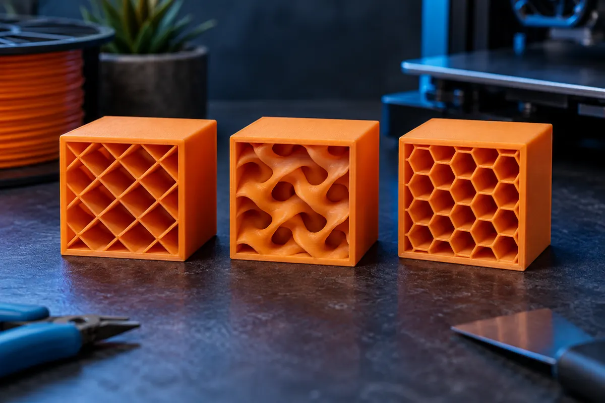
Technical context
Select pattern and density for the loading case and top-surface support. Increasing walls can be more useful than increasing sparse infill for some parts, but the decision depends on geometry and force direction. Inspect paths rather than assuming equal percentages produce equal behavior.
Practical workflow
Compare two sliced variants with the same shell and then validate representative parts. If sparse infill leaves a weak top, adjust top-layer thickness or support strategy instead of merely maximizing density. Strength claims require relevant testing; slicer previews cannot certify load-bearing use.
Calculation and units
Mass g = cm³ × density g/cm³; volume = mass/density. 1 cm³ = 1 mL = 1,000 mm³.
Worked example
20 solid cm³ at 1.24 g/cm³ weigh 24.8 g. A 20% infill print is not automatically 20% of that because walls remain.
Validate the outcome
Mark generic presets as estimates. Printed apparent density includes voids and is different from raw polymer density.
Account for shells before changing density
Imagine 35 g shell, 15 g infill and 5 g support: 55 g total. Saving 5 g infill leaves 50 g, about 9.1% less total, not a reduction proportional to the infill slider. Small thin-wall parts can be almost all shell. Equal nominal density across patterns also does not imply equal path length, acceleration or top support. Inspect sliced variants and validate the loading mode rather than treating percentage as a strength certificate.
Top layers bridge the internal gaps
Sparse paths support the first solid top layer. Large gaps can make it behave like a bridge and sag before later layers cover it. More top thickness or a different internal pattern may improve the surface without filling the whole part solid. Test a representative section to minimize trial waste. A 100% setting is still not a guarantee of void-free material or perfect bonding; directly test sealing or loading requirements.
Separate structural and cosmetic goals
For a decorative model, infill may mostly support the roof and preserve shape during handling. A loaded bracket needs a defined force direction and suitable shell, infill and orientation combination. Changing the pattern to improve a visible top is different from certifying a functional part. Keep the purpose in the profile notes and compare accepted quality, total grams and time together when choosing between variants.
Changing one consumption category
| Category | Original | Variant |
|---|---|---|
| Shell | 35 g | 35 g |
| Infill | 15 g | 10 g |
| Supports | 5 g | 5 g |
| Total | 55 g | 50 g |
A repeatable infill experiment
Keep geometry, wall count, top/bottom thickness, material and orientation fixed while comparing patterns or sparse density. Slice each variant and record the mass breakdown and duration. Examine whether internal paths support the first top layer and whether the feature's load path actually uses them. For a functional part, perform a relevant controlled test rather than assuming a preferred pattern makes every geometry stronger.
Compare accepted output and finishing effort. Lower sparse mass can worsen top surfaces and require more sanding or rejects, while a denser variant can add time without meaningful function. If walls dominate consumption, focus design or shell decisions before expecting a major infill saving. A 100% slider cannot prove void-free production, so sealing and critical load requirements still need direct inspection and testing.
Is 20% infill one fifth of solid part mass?
Usually not for the whole job. Walls, top/bottom skins, supports and startup remain outside the sparse infill setting. Their share can dominate a small or thin part. The pattern and slicer geometry also affect consumption. Read the actual mass breakdown, change only the intended category and compare the sliced total. A simple solid-volume-times-density calculation cannot directly replace an ordinary partially filled job estimate.
Can 100% infill guarantee a watertight part?
No. It is a path-planning choice, not proof of void-free deposition, bonding or seam integrity. A sealing requirement needs an appropriate material, process and inspection method. Increasing infill alone can add time without solving a leak through a seam or poorly bonded wall. Evaluate the actual requirement with a representative specimen and keep test conditions documented, rather than turning a maximum slider into a performance guarantee.