
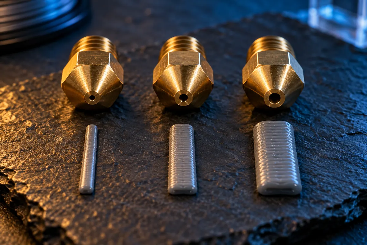
Technical context
A 0.4 mm nozzle is a common versatile starting point. A 0.6 mm option can suit larger functional parts when fine XY detail is less important, while 0.8 mm can suit coarse large features. These are job-selection examples, not guarantees for every printer or filled material.
Nozzle opening cross-sectional area
View data table
| Comparison | mm² |
|---|---|
| 0.4 mm | 0.1257 |
| 0.6 mm | 0.2827 |
| 0.8 mm | 0.5027 |
Practical workflow
Slice the same model using properly configured nozzle profiles and compare time, flow and retained features. A larger nozzle with taller layers may hit the existing hotend's flow ceiling, limiting the expected time saving. Choose abrasion resistance independently when the material requires it.
Calculation and units
Rectangular Q = width × height × speed. Stadium A = h × (w ? h) + ?h²/4 for w ? h, then Q = A × speed.
Worked example
0.45 × 0.20 mm at 100 mm/s requires 9 mm³/s rectangularly, or 8.14 mm³/s with rounded geometry.
Validate the outcome
Match slicer geometry and test actual nozzle, temperature and filament. Poor adhesion can precede visible under-extrusion.
Choose from the part's requirements
A 0.4, 0.6 or 0.8 mm nozzle is a tooling choice, not a universal quality ranking. Start with the smallest necessary feature, desired surface, wall strategy and production volume. A larger nozzle can support wider paths and thicker layers when the machine and material permit them, but it does not make every job faster. A smaller nozzle can suit finer features while adding path count or restricting useful throughput. Compare candidate profiles using the same model and a clear acceptance criterion instead of selecting by diameter alone.
Line width and diameter are not identical
The slicer chooses extrusion width, and that width need not equal the hole diameter of the nozzle. Consequently diameter alone cannot calculate volumetric demand or the number of walls. Use the actual planned widths and heights in the flow and wall tools. Inspect thin features in the preview because the selected strategy may create variable-width paths or omit details. A larger nozzle may print a broad wall efficiently while struggling with a fine embossed marking. Those two requirements can coexist on one part and need an explicit compromise.
Compare geometric throughput fairly
For an illustrative profile, a 0.45 mm-wide path at 0.20 mm height and 100 mm/s demands 9 mm³/s by the rectangular approximation. A 0.66 mm-wide path at 0.30 mm height at that same speed demands 19.8 mm³/s. The latter is 2.2 times the material demand. If the tested hotend limit remained 12 mm³/s, the corresponding flow-limited speeds would be about 133.3 and 60.6 mm/s. The larger path may still cover an area efficiently, but maintaining the original speed requires substantially more capacity.
Time depends on more than line count
Wider lines can reduce the number of paths needed for a region, while greater layer height can reduce vertical passes. Both can also change surface stepping, small features and overhang behaviour. Acceleration, cooling and flow caps determine how much of the nominal saving becomes real time. Slice each candidate with an appropriate profile rather than changing only the nozzle label. Compare material, supports and observed results as well as estimated time. A faster estimate is not a successful alternative if the part loses a required feature or fails its functional check.
Match nozzle construction to material and machine
Diameter does not describe the nozzle's wear resistance, heat transfer or installation requirements. Use a nozzle compatible with the hotend and selected material, following its documented fitting procedure. Abrasive formulations may require an appropriate wear-resistant option; that choice can affect the tested operating conditions. Do not assume one installation sequence or torque applies to every system. After a hardware change, verify first-layer behaviour and material deposition before returning to production. Keep the prior known-good profile until the new setup passes its validation.
Use a controlled selection trial
Choose a representative part containing the critical details and print accepted candidate profiles under comparable conditions. Record nozzle, width, height, tested flow limit, time, consumption and the acceptance result. For a broad functional bracket, larger paths may be useful; for small text or interfaces, the finer option may remain preferable. The comparison should answer whether the part meets its requirements at an acceptable total cost. Avoid turning one good demonstration print into a claim that a nozzle size is best for every material or geometry.
Does 0.8 mm automatically print twice as fast as 0.4 mm?
No. Width, height, flow capacity, cooling, acceleration and geometry determine the actual job time.
Should line width always equal nozzle diameter?
Not necessarily. Use the actual validated slicer setting and inspect generated paths.