
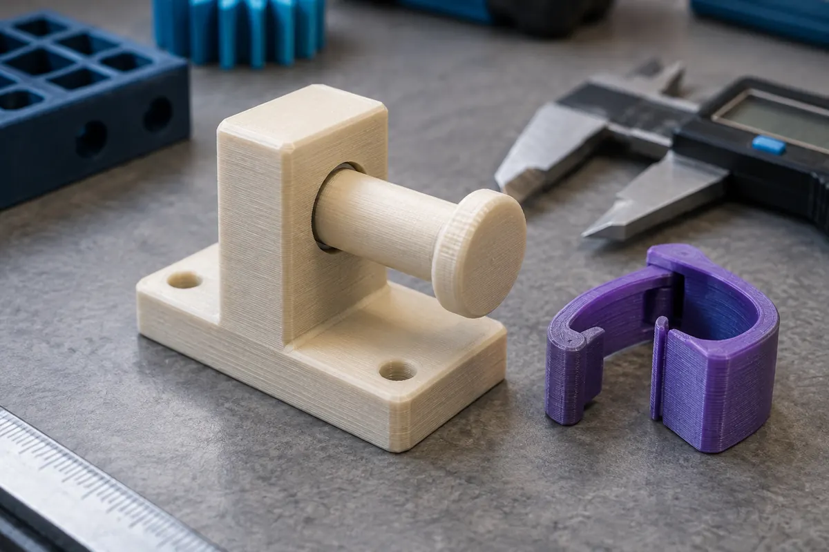
Technical context
Print a fit coupon with the same material, orientation and layer profile as production. Measure several mating sizes rather than choosing one universal gap. For a pin and hole, distinguish diametral clearance from radial gap: a 0.2 mm diameter difference means 0.1 mm space per side when centered.
Diametral versus radial clearance
View data table
| Comparison | mm |
|---|---|
| Diametral | 0.2 |
| Radial | 0.1 |
Practical workflow
Determine whether the error is proportional, constant or local before scaling the whole assembly. Snap fits also depend on flexibility and layer orientation. A sliding fit tested once does not establish repeatable production tolerance; keep measurements from multiple parts.
Calculation and units
Scale = target/measured. Shrinkage = (nominal ? measured)/nominal. Compensation for fraction s = 1/(1 ? s).
Worked example
100 mm measured at 99 mm needs 101.0101%. A 10 mm detail at 9.8 mm needs another factor, suggesting other errors.
Validate the outcome
Measure several sizes and directions. Use hole compensation or CAD clearance for local mating errors.
Specify the required relationship
Tolerance is the permitted variation of a dimension; clearance is the intended gap between interacting features. A printer's observed error is another quantity. Keeping these distinct avoids the common habit of calling every loosened hole a tolerance adjustment. Write down what the assembly must do: move freely, locate, grip or accept a fastener. Then identify the relevant dimensions and acceptance criteria. This article provides a measurement method, not a universal clearance that can be transferred to every material, printer and orientation.
Use a consistent gap convention
For a circular shaft and hole, diametral clearance equals hole diameter minus shaft diameter. Radial clearance is half that amount. A 10.2 mm hole around a 10.0 mm shaft has 0.2 mm diametral and 0.1 mm radial nominal clearance. These are illustrative geometry values, not a recommended fit. Mixing radial and diametral language can double or halve an intended change. For a sliding rectangular interface, define whether the stated gap applies per side or across the entire dimension before modifying the model.
Measure both mating features
A failed fit does not show which part is wrong. Measure the cooled shaft and hole separately, using suitable methods for their shapes. External caliper readings and small internal holes have different measurement limitations. Record nominal and observed values with orientation and first-layer location. If the shaft is oversized and the hole undersized, changing only one can hide the other process error. A printed go/no-go coupon can help evaluate function when a direct measurement is difficult, but its acceptance still needs a clearly defined application requirement.
Distinguish offsets from proportional errors
Check more than one feature size. A 0.3 mm deviation on both a 10 mm and 50 mm feature suggests a different correction model from a one-percent error on each. Hole shape, line placement and first-layer bulge can create local effects. Uniform scaling changes everything, including interface spacing and outer dimensions. Use the shrinkage calculator only when repeated measurements support a proportional relationship. For local fit, consider CAD clearance or an appropriate slicer compensation and verify exactly which surfaces it affects.
A controlled fit-coupon experiment
Create a small set of variants around the intended interface, labelled with their actual dimensions or gap convention. Keep material, nozzle, orientation and profile constant. Print and cool them under comparable conditions, then test the real mating part. Record fit, movement, surface damage and any required force rather than only declaring one variant best. The useful range is specific to this test and function. Repeat if production orientation or material changes, and do not present a coupon result as a guaranteed capability of every printer.
Account for use, not only initial assembly
A part that assembles once may bind under load, temperature change or repeated motion. Surface texture and wear can affect a sliding interface. Flexible parts may deform during measurement or assembly, making nominal dimensions an incomplete description. Evaluate the actual intended use and any relevant conditioning state. Critical or load-bearing applications require their own engineering assessment; the calculators do not certify them. Keep geometric correction separate from functional testing so a clean measurement does not replace proof that the assembly behaves as required.
Keep the accepted configuration traceable
Save the accepted CAD dimensions, compensation settings, orientation and material with the inspection results. Avoid applying the same adjustment in both CAD and slicer unknowingly. When sending the design elsewhere, state whether the exported file already includes the correction. Recheck after nozzle changes, material changes or substantially different print settings. A documented fit solution is more valuable than a single unexplained gap value, because another person can reproduce the conditions and understand which assumptions must be checked again.
Is clearance the same as dimensional accuracy?
No. Clearance is an intended gap; accuracy describes observed deviation from a nominal dimension.
Is one gap value safe for every FDM assembly?
No universal value is justified. Test the actual geometry, material, orientation and intended function.