
Technical context
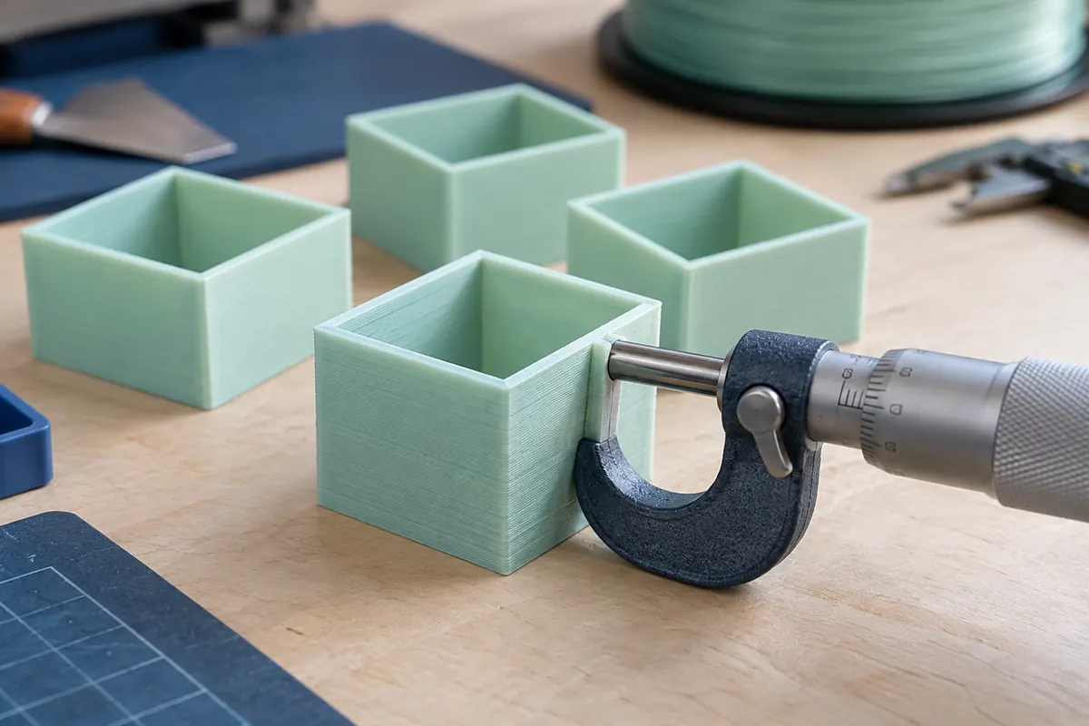
Print a controlled specimen, assess several cooled measurements or a documented top-surface test, and change one parameter at a time. The nominal width entered in a slicer is not automatically identical to every measurable surface width on a real rounded bead.
Apply the modifier to the current ratio
View data table
| Comparison | ratio |
|---|---|
| Current | 0.98 |
| +2 % | 0.9996 |
Practical workflow
Validate the proposed multiplier on a representative part. A smooth top can coexist with dimensional errors, and a single thin wall can mislead a coarse caliper. Large correction factors warrant checking clogs, diameter settings, gear grip and firmware flow before saving the profile.
Calculation and units
New ratio = current ratio × target/measured wall. 1.00 means 100%; slicer and firmware multipliers can multiply.
Worked example
1.00 ratio, 0.45 mm target and 0.47 mm measured suggest 0.95745. Reprint and inspect surfaces and dimensions.
Validate the outcome
Measure cooled samples repeatedly. Large corrections may indicate hardware or feed issues instead of a simple flow mismatch.
Match the test to the wall model
A wall method assumes a suitable specimen and an instrument that resolves the correction. Coarse calipers squeezing a flexible or uneven wall can mislead. Measure several cooled points away from corners and record wall generator and width. A visual top-surface method instead evaluates gaps and scarring. Follow the manufacturer's documented procedure and verify on representative geometry rather than treating one measurement as permanent truth for every filament.
Do not correct the same quantity twice
Firmware flow 95% and slicer ratio 0.98 can combine to 0.931. Raising the slicer to 1.00 does not restore an overall 100% process. Record both controls and keep a known baseline during calibration. Confirm filament diameter, since it controls computed feed. Density affects reported mass instead. Separating these controls prevents a metadata correction from changing good deposited geometry or hiding a genuine feed problem.
Validate more than a smooth top
Reprint the same controlled specimen after a modest correction, then inspect dimensions, surface and bonding. A smooth-looking top can coexist with poor tolerances or overfilled corners. If the needed ratio is extreme, investigate drag, slipping gears, blockage and excessive flow demand rather than repeatedly increasing it. Keep material, temperature and speed unchanged during the comparison and preserve the accepted profile with the test evidence.
Combined quantity multipliers
| Firmware | Slicer | Combined |
|---|---|---|
| 100% | 1.00 | 1.00 |
| 95% | 0.98 | 0.931 |
| 95% | 1.00 | 0.95 |
An error-aware wall-test worksheet
Take several readings on the middle of each suitable cooled wall and record their spread as well as the mean. If readings vary by 0.04 mm while the intended correction is 0.01 mm, the instrument and specimen do not strongly resolve that correction. A top-surface comparison or better measurement method may be more useful. Avoid interpreting excessive numerical precision from the ratio formula as reliable physical certainty.
After the proposed change, repeat the same specimen with the same nozzle, temperature, width and speed. Compare top gaps, scarring, dimensions and bonding. Save both the old and accepted ratios and the reason for choosing the new value. If hardware is inconsistent, solve feeding or obstruction first; otherwise the multiplier can conceal a fault rather than characterize the filament. Material profiles should describe verified conditions, not unexplained numbers copied from another machine.
Should I rely on one thin-wall measurement?
It is a weak basis when the wall is uneven or the instrument cannot resolve the change. Take repeated cooled readings away from corners and inspect the spread. Compare the method with the actual wall generator and use a documented visual method when appropriate. Then validate the proposed ratio on representative geometry. The mathematical target/measured equation is straightforward, but its physical reliability depends on the specimen and measurement contract.
Can I fix under-extrusion by setting a large multiplier?
Only if a correctly diagnosed quantity mismatch is the cause, and even then the correction needs validation. Drag, gear slipping, a partial blockage or excessive flow can produce similar symptoms. A larger request against a restriction can worsen feed failure. Check a known-good low-demand test and hardware first, then change the relevant control. Save the accepted ratio with conditions rather than adopting an unexplained extreme value.