
Technical context
Use a manufacturer-supported height range for the selected nozzle. A layer taller than the nozzle opening leaves little controlled flattening; very thin layers add time and can make feeding more sensitive. Nominal nozzle diameter is also different from slicer extrusion width.
Three distinct dimensions
View data table
| Comparison | mm |
|---|---|
| Nozzle | 0.4 |
| Line width | 0.45 |
| Layer height | 0.2 |
Practical workflow
A larger nozzle can print the same modest height with wider paths, or larger heights with much higher volume demand. Decide height from the surface you need, then check width, flow and cooling. This article concerns compatible geometry; nozzle selection for specific jobs is a separate comparison.
Calculation and units
For positive H: 1 if H ? first layer, otherwise 1 + ceil((H ? first layer)/normal layer).
Worked example
20 mm at 0.20 mm first and normal layers gives 100 layers. Changing only normal height to 0.10 mm gives 199.
Validate the outcome
Fine Z layers do not improve XY details below path width. Check actual layer sequence in the slicer.
Opening, width and height are separate
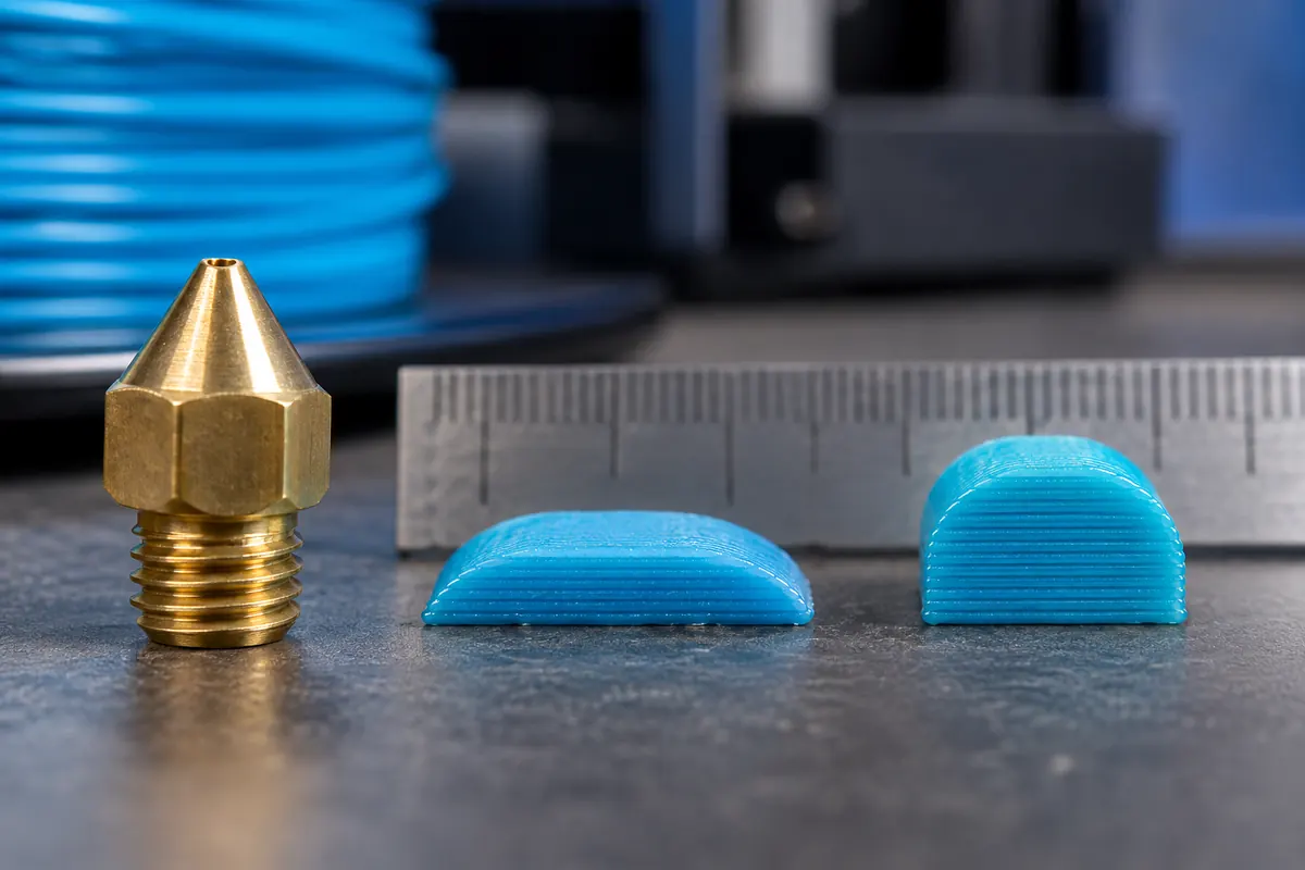
A 0.4 mm nozzle is the nominal opening; a profile can deposit a 0.45 mm-wide path at 0.20 mm height. The bead flattens, so width need not equal opening diameter. Use supported profiles rather than forcing all width fields to the nozzle label. Manufacturer height ranges are process guidance, not a guarantee of quality for every material. A compatible height still needs correct temperature, flow and cooling.
Higher layers can consume the speed benefit
At 100 mm/s, rectangular 0.45 × 0.20 mm asks for 9 mm³/s; 0.65 × 0.30 mm asks for 19.5. With safe capacity 12, the second geometry caps at about 61.5 mm/s. Fewer layers and paths can still save time, but requested speed exaggerates the advantage. After a nozzle change, update the machine profile and re-slice thin features, supports and clearances, not just the layer-height field.
Choose geometry from the required feature
A sloping visible surface may justify finer height while a broad functional wall may benefit from wider paths. Decide the surface and minimum feature first, then check a compatible nozzle/height/width combination against available flow. The separate nozzle-size comparison evaluates which opening suits a whole job; this article explains why opening and height cannot be treated as the same resolution setting.
Opening and deposition dimensions
| Quantity | Example | Meaning |
|---|---|---|
| Nozzle | 0.4 mm | Nominal opening |
| Width | 0.45 mm | Planned flattened path |
| Height | 0.20 mm | Vertical layer increment |
A controlled nozzle-height comparison
Start from supported profiles for each nozzle rather than modifying a single old profile's height. Slice one model with the same purpose and compare retained thin features, wall layout, support, flow and estimated duration. A fine visible curve may benefit from small height even with a larger opening; a tiny XY feature may need a smaller suitable nozzle regardless of height. Name the feature driving the choice.
Print representative sections and inspect the accepted result after cooling. Record nozzle, width, height, material, temperature and observed defects. Check whether thicker paths exceed the safe flow cap and whether the expected time saving survives acceleration and cooling. A favorable result on one broad wall does not prove the same combination works for text, overhangs or a fitted joint. Preserve the design constraints as well as the speed comparison.
Does nozzle diameter define extrusion width exactly?
No. It describes the nominal opening, while deposition flattens a path whose width depends on the profile and process. A supported 0.4 mm nozzle profile can use a nominal 0.45 mm path. Variable-width slicing can also change width along a feature. Treat diameter, width and height as related but separate inputs, and inspect the actual generated geometry. The manufacturer's supported profile is a better starting point than forcing every width field to equal the opening.
Can I choose layer height from a universal nozzle percentage?
Use supported material and printer guidance as a starting range, then validate the required surface and bonding. A familiar percentage is a heuristic, not certification for every nozzle construction or polymer. Extremely tall layers may lack controlled flattening, while very fine layers increase work without helping XY details. Check width and volumetric demand together and compare sliced profiles rather than assuming one ratio determines all quality.