
Technical context
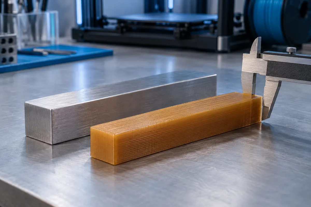
Measure cooled specimens of several sizes in each relevant axis and keep the process consistent. A nearly constant 0.2 mm error across small and large holes suggests an offset mechanism; an error growing proportionally with length better supports a scale model.
Measure before compensating
View data table
| Comparison | mm |
|---|---|
| Target | 100 |
| Measured | 99 |
Practical workflow
Use compensation conservatively and inspect fit again. Warping creates curved or lifted geometry that cannot be flattened by uniform scaling. First-layer expansion and orientation-sensitive accuracy may instead call for local CAD adjustment or slicer compensation.
Calculation and units
Scale = target/measured. Shrinkage = (nominal ? measured)/nominal. Compensation for fraction s = 1/(1 ? s).
Worked example
100 mm measured at 99 mm needs 101.0101%. A 10 mm detail at 9.8 mm needs another factor, suggesting other errors.
Validate the outcome
Measure several sizes and directions. Use hole compensation or CAD clearance for local mating errors.
Test proportionality with two sizes
A 100 mm bar at 99 mm and a 50 mm bar at 49.5 mm are both 1% short, consistent with proportional behavior in those conditions. Compensation is 1/0.99, about 1.010101. If both bars are instead 0.2 mm short, their percentage errors differ and a constant offset is more plausible. Measure relevant axes separately after controlled cooling and keep measurement location away from a first-layer flare.
Global scale can harm correct features
If only holes are small but exterior length is correct, whole-part scaling also enlarges the good exterior. Local CAD clearance or appropriate slicer hole compensation may be better. An elephant-foot adjustment addresses the first layer rather than inventing a material shrink percentage. For an assembly, verify both mating pieces and clearance after every compensation; correcting one outside length does not prove a sliding or snap-fit joint works.
Warping needs a shape check before a scale factor
A curled base has shape distortion that cannot be represented by one shrinkage percentage. Check flatness and straightness first and investigate thermal gradients, adhesion and geometry. Applying a scale to a distorted specimen can make its nominal extents match while retaining an unusable shape. Keep process correction and geometric compensation separate and validate the final function under actual service conditions.
Proportional versus offset example
| Nominal | Measured | Shortfall |
|---|---|---|
| 100 mm | 99 mm | 1% |
| 50 mm | 49.5 mm | 1% |
| 100 mm | 99.8 mm | 0.2% |
| 50 mm | 49.8 mm | 0.4% |
Construct a dimensional-error decision process
First confirm the model's units and nominal dimensions. Then measure cooled parts away from first-layer flare, using consistent instrument and locations. Compare several nominal sizes. Proportional errors suggest a scale hypothesis; constant offsets suggest local compensation; curved or lifted geometry suggests warping. Only then choose the relevant tool. A numerical scale can make one measured length correct while harming other dimensions.
Validate the compensation on a second specimen and the actual mating assembly. Measure both pin and hole and distinguish diametral from radial clearance. A 0.2 mm diameter difference gives 0.1 mm per side when centered. Print orientation and material conditioning can alter behavior, so preserve them during comparison. The goal is repeatable function, not a perfectly matching single measurement obtained by hiding the underlying process defect.
Should I apply one factor to X, Y and Z?
Only when measurements support that assumption. Directional printing behavior, cooling and geometry can produce different errors by axis. Measure relevant features in several sizes and compare proportionality before choosing uniform or directional compensation. If only one local feature is wrong, global scaling may damage correct geometry. Validate both the corrected dimensions and the actual assembly function; a single matching bar does not establish every fit.
Why does 1% shrinkage need more than 101% scale?
The printed dimension is the model dimension multiplied by 0.99 under that proportional assumption. To reverse it, divide the target by 0.99, giving about 1.010101 or 101.0101%. Simply adding 1% is a close approximation at small shrinkage, not the exact inverse. Use the proper denominator and keep its uncertainty visible; more decimal places do not validate whether the original error really was proportional shrinkage.