
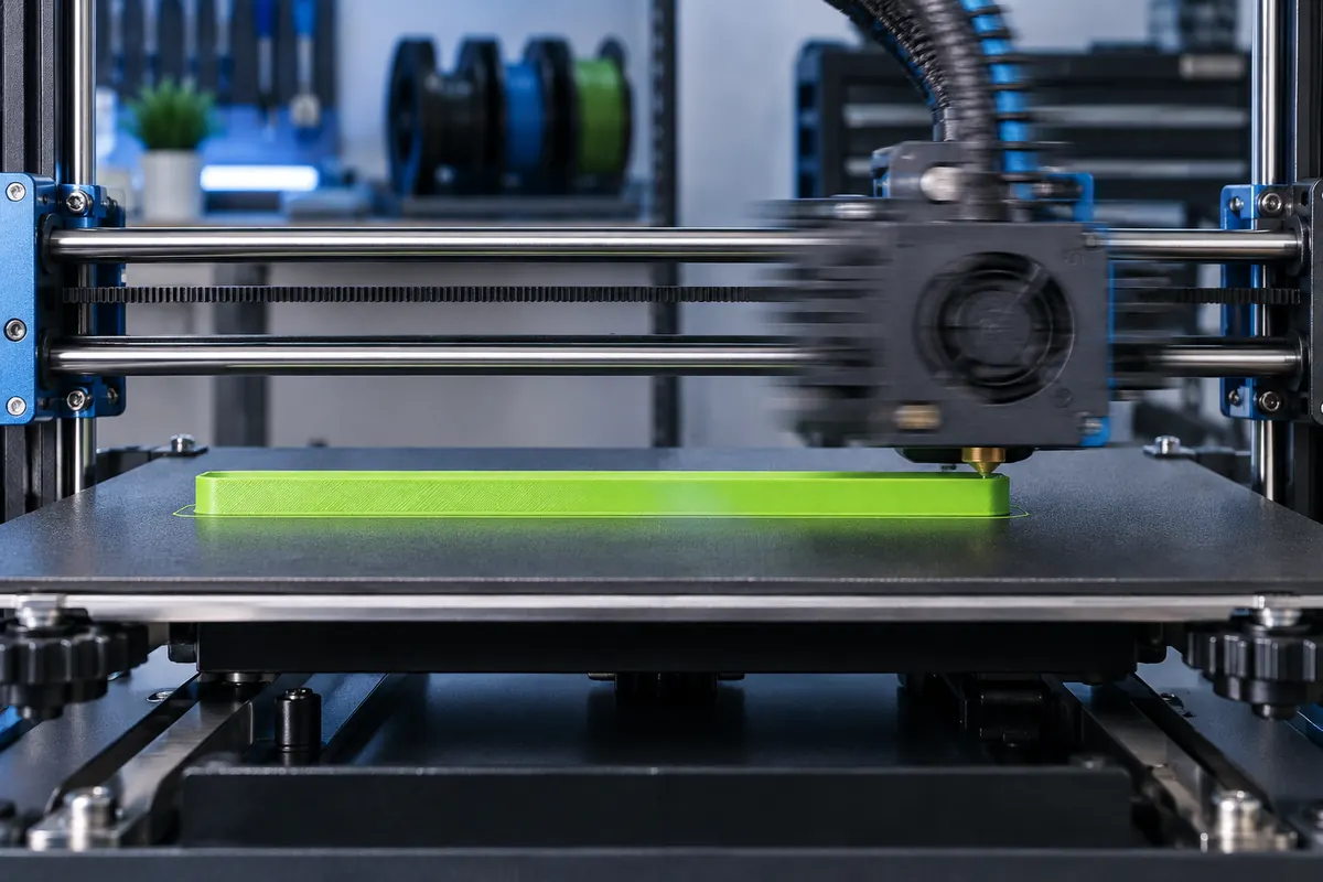
Technical context
A short line may finish accelerating only as it needs to brake. Raising its requested speed therefore may not change elapsed time much. A long infill stroke can instead reach the flow limit, making extrusion cross-section as important as motion settings.
Time at constant travel speed
View data table
| Comparison | s |
|---|---|
| 40 mm/s | 2.5 |
| 80 mm/s | 1.25 |
| 120 mm/s | 0.8333 |
Practical workflow
Inspect speed and volumetric previews and compare changes using the same part. Separate travels from extrusion speed. If a faster profile creates rejects or excessive finishing, cost per accepted job can rise even when the displayed slicer duration falls.
Calculation and units
Speed mm/s = safe mm³/s/cross-section mm². Use rectangular or rounded geometry consistently.
Worked example
12 mm³/s divided by a rectangular 0.60 × 0.30 mm cross-section gives 66.7 mm/s. Doubling height halves this limit.
Validate the outcome
Use measured profile-specific flow limits with quality margin. Re-test after nozzle or material changes.
Short lines may never reach their target
Ignoring junction effects, reaching 100 mm/s from rest at 1,000 mm/s² needs five millimeters. Braking needs another five. A shorter isolated segment cannot spend distance at that target under the simplified model. Real look-ahead connects moves, so this illustrates acceleration rather than simulating a print. Examine whether the part is dominated by short perimeters, long infill, travel or cooling before choosing a speed intervention.
Optimize the active constraint
Long infill at the melt limit cannot become useful output by raising motion speed. A tiny tower controlled by layer cooling can benefit from different scheduling or multiple copies only if material and quality remain acceptable. If finishing dominates turnaround, faster printing may save little workshop labor. Compare each change at unchanged geometry and acceptance criteria, then record actual elapsed duration and any live overrides.
A fast profile can cost more per accepted job
Suppose a slower profile completes in six hours with stable output, while a four-hour profile needs frequent reprints or thirty extra minutes of finishing. The faster slicer number alone cannot establish efficiency. Include yield, machine occupancy and active labor in the comparison. Requested print speed, whole-job duration and accepted-part cost answer different questions, so report all relevant measures instead of promoting only the highest millimeters-per-second value.
Speed constraints to diagnose
| Symptom | Likely constraint to inspect |
|---|---|
| Long thick infill slows | Volumetric demand |
| Tiny layers slow | Cooling minimum time |
| Short segments never cruise | Acceleration and junctions |
| Long turnaround after print | Finishing and inspection |
Build a time budget from actual constraints
Separate machine motion, thermal waits, layer cooling and manual turnaround. Identify the dominant portion using the sliced preview and actual job records. Increasing a long infill speed helps only until flow or motion becomes the limit. Increasing short-feature targets can have little effect when acceleration prevents cruising. For a small tower, layer cooling can be decisive even with ample melt capacity.
Then compare a controlled change at the same part and acceptance standard. Record actual elapsed time, overrides, accepted yield and finishing minutes. A reduction from six to four machine hours does not establish a cheaper job if it creates repeated failures or extra handling. Use the cost and finish-time tools to explain the impact on the full workflow. Faster requested movement, shorter print duration and earlier usable-part delivery are related but distinct results.
Why does changing200 to300 mm/s barely change time?
The requested value may not be the active limit. Short paths can be acceleration-limited, thick paths flow-limited and small layers cooling-limited. A feature-specific lower speed may also govern. Inspect the relevant previews and the machine profile, then test a controlled change on the same model. Do not assume the requested peak is reached throughout the job, and do not turn a headline speed ratio into a guaranteed whole-print time ratio.
Should I raise every feature speed equally?
No universal increase suits every region. Outer walls, overhangs, bridges and infill have different quality and demand constraints. Identify the actual bottleneck and preserve required surfaces and bonding. A volumetric cap can help prevent overloaded paths, but cooling and motion still require suitable settings. Compare accepted yield and finishing effort as well as duration so an apparently faster slice does not conceal a less reliable or more expensive production process.