
Technical context
Check spool drag, gear grip, nozzle condition and the correct filament diameter setting. Compare a low-demand print with the failing fast region. If only high-flow infill fails, a capacity limit is more likely than a universal mechanical feed calibration error.
Practical workflow
Restore a known-good temperature and profile, then run controlled feed and flow tests as appropriate. Raising the multiplier against a restriction may cause grinding or missed steps. Verify surfaces and bonding after correction rather than accepting a filled-looking exterior alone.
Calculation and units
New E-steps = old × commanded/measured. Klipper rotation distance corrects in the opposite direction.
Worked example
93 steps/mm with 100 mm commanded and 96 mm measured gives 96.875 steps/mm. A 120 mm marking is not automatically 120 mm extrusion.
Validate the outcome
Check gear grip and manufacturer procedure. Never use E-steps to compensate a clogged nozzle.
Describe where material is missing
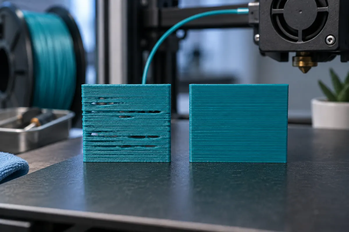
Under-extrusion can appear as gaps, thin lines, incomplete top layers or weak deposition. First record whether it affects every feature, only fast infill, only restart points or a region of the part. Those patterns suggest different investigations. Save the file, profile and material used for the failed sample. A larger extrusion multiplier is not a diagnosis. It may improve one symptom while overfilling slower regions. Choose a small relevant comparison that can distinguish a sustained feed problem from a speed- or transition-related defect.
Inspect the entire filament path
Check that the spool turns freely and that filament travels without unexpected resistance. Look for a tangled winding, sharp routing, damaged tube or material caught at the inlet, using the machine's guidance. Examine drive-gear grip and debris without changing several adjustments simultaneously. Intermittent restriction can make a feed measurement vary widely. Increasing mechanical calibration to compensate that slip creates another error when the restriction disappears. Restore reliable movement before treating the observed shortage as a stable ratio correction.
Nozzle condition and temperature need evidence
A partial obstruction or unsuitable thermal condition can limit deposition, but the appropriate inspection and cleaning procedure depends on the hotend. Follow documented service guidance rather than improvised commands or disassembly. Check that the selected temperature is appropriate to the actual material and machine. Raising it may change a symptom but can introduce other effects; reducing speed provides another controlled comparison. Keep material condition consistent and record popping or surface changes as observations rather than proof of one cause.
Check demand against tested flow
If gaps occur only during fast, broad or thick extrusion, calculate the approximate volume demand. A 0.45 mm line at 0.20 mm and 100 mm/s requires 9 mm³/s by the rectangular model. At 200 mm/s it requires 18 mm³/s. If your validated limit is 12, the latter exceeds that planning cap. A clean slower version supports investigating throughput rather than raising global flow. The tested cap must match nozzle, material and temperature; the calculator cannot supply a universal hotend capacity.
Separate mechanical feed calibration from material flow
E-steps or the relevant firmware mechanical parameter describes movement. Material flow ratio adjusts deposited amount after reliable movement is established. Pressure advance concerns transitions. These are not interchangeable fixes. A repeatable commanded-versus-measured feed test can justify a mechanical ratio correction, while inconsistent readings call for troubleshooting. Do not paste an E-steps value into a Klipper rotation-distance field; their conventions differ. After any justified mechanical change, repeat the physical test before proceeding to a material-specific flow experiment.
Inspect active overrides and the sliced file
A slicer ratio, firmware multiplier and operator override can combine. Confirm their actual values during the test. If the file was produced with another material profile or changed afterwards, comments may not describe the active job. Examine the actual paths, especially top layers and narrow areas that may be strategy-related rather than globally underfilled. A shortage confined to restarting after travel can involve retraction or transient behaviour. A shortage confined to the first layer needs its own contact and surface checks.
Use one-variable comparisons
Print a baseline and one deliberate alternative. For a throughput hypothesis, reduce demanding speed while preserving other settings. For a material-flow hypothesis, use the documented flow test after hardware is stable. Record gaps, surface, bonding and dimensions, not just whether one patch looks smoother. Reverse an ineffective change before testing another cause. If several variables move at once, an improvement does not reveal which one mattered. A short evidence log prevents an accumulation of compensating settings that later fails on a different part.
Validate the accepted part and profile
After identifying a candidate solution, print representative geometry containing both ordinary and demanding regions. Inspect layer connection and function as well as surface. A part with apparently repaired gaps can still be weak if bonding remains poor. Save material, nozzle, temperature, flow limit and active overrides with the accepted setup. Recheck after a meaningful hardware or profile change. Persistent missing material deserves a cause-based investigation; the goal is reliable deposition across the intended operating range, not hiding a defect behind an increasingly large global multiplier.
Use the defect pattern to choose a test
| Pattern | Hypothesis | Controlled comparison |
|---|---|---|
| Only fast infill has gaps | Demand may exceed tested throughput. | Reduce demanding speed while preserving other settings. |
| Shortage follows travel | Restart or transient behaviour may matter. | Inspect retraction and actual restart paths. |
| Irregular shortage everywhere | Feed resistance or inconsistent grip may matter. | Inspect the mechanical path and repeat measured feed tests. |
Should I fix gaps by increasing the flow ratio?
Only after diagnosing the pattern and establishing reliable hardware and tested throughput. A global increase can overfill unaffected features.
Why do gaps appear only in fast infill?
That pattern can support a throughput investigation. Calculate demand and compare a controlled slower test, while checking other causes.