
Technical context
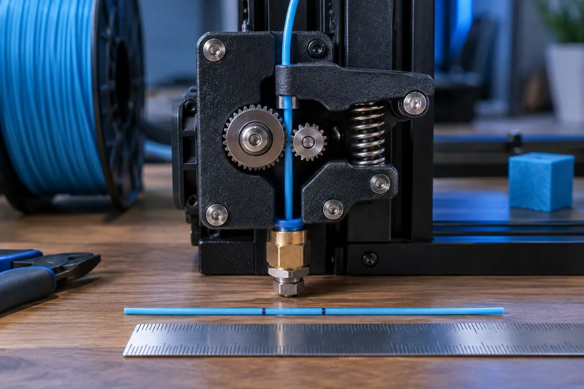
Identify firmware and follow the manufacturer's measurement procedure. Measure from a fixed reference, command a known feed and calculate actual movement from the difference. Restriction in the hotend and gear slipping can invalidate the observation if the procedure does not control them.
Commanded and measured extrusion
View data table
| Comparison | mm |
|---|---|
| Commanded | 100 |
| Measured | 96 |
Practical workflow
Marlin commonly uses steps per unit, while Klipper uses rotation distance. The correction directions differ. Record the original value, verify repeated measurements and confirm persistence after restart. Do not change XYZ steps from one printed cube to hide shrinkage.
Calculation and units
New E-steps = old × commanded/measured. Klipper rotation distance corrects in the opposite direction.
Worked example
93 steps/mm with 100 mm commanded and 96 mm measured gives 96.875 steps/mm. A 120 mm marking is not automatically 120 mm extrusion.
Validate the outcome
Check gear grip and manufacturer procedure. Never use E-steps to compensate a clogged nozzle.
Make the feed measurement unambiguous
Mark filament 120 mm from a fixed reference, command 100 mm and measure 24 mm remaining. Actual feed is 120 ? 24 = 96 mm, not 24 or 120. At 93 steps/mm, the correction is 93 × 100/96 = 96.875. Record initial and remaining distances and repeat before editing firmware. Marker thickness, angled measurements and moving references can dominate a small correction.
Rotation distance corrects oppositely
More steps per millimeter command more motor movement, so underfeed raises that setting. Rotation distance describes travel per rotation; its correction is current rotation distance × measured/commanded. Using the steps equation for rotation distance changes the value in the wrong direction. Identify firmware and follow the manufacturer's persistence procedure. The web calculator proposes a number only and must never send machine commands or assume it can modify a connected printer.
Keep mechanical calibration separate from material behavior
If repeated feed measurements vary, investigate hardware grip or measurement technique before averaging an unstable system. A material's extrusion multiplier can then fine-tune a stable process, but should not become a substitute for feed accuracy. Do not infer XYZ step changes from a printed cube: shrinkage, first-layer flare and measurement offsets can alter part dimensions without a mechanical step-distance error.
Measured-feed worksheet
| Item | Value |
|---|---|
| Initial mark | 120 mm |
| Remaining mark | 24 mm |
| Actual feed | 96 mm |
| Commanded feed | 100 mm |
| Original steps | 93/mm |
| Proposed steps | 96.875/mm |
Establish repeatability before saving firmware
Measure at a stable reference with the manufacturer-approved feed procedure. Repeat the known command and compare actual movement; inconsistent readings mean the test setup or mechanics needs investigation before changing the ratio. Preserve the original setting and verify that a proposed change corrects the feed in a second run. Save and restart only under the printer's documented workflow, then check persistence.
This calibration should not become a catch-all for poor printed surfaces. If commanded feed is correct but high-flow printing fails, inspect melting demand and restriction. If printed outer dimensions vary with size, investigate proportional shrinkage or offsets rather than adjusting motor steps from one cube. Material flow, motion calibration and thermal behavior are separate mechanisms. Maintaining that separation prevents one compensating error from masking another.
Must every factory printer be recalibrated immediately?
Follow the manufacturer's guidance. A properly configured factory system may already have correct mechanical values, and a noisy measurement can make them worse. Calibration is appropriate when hardware or evidence indicates a feed-distance problem, not simply because a calculator exists. Preserve the original setting and demonstrate repeatable incorrect feed before proposing a correction. Material-specific flow and high-speed melt limits are different investigations.
Can I paste the result directly into any firmware?
No. Confirm whether the system uses steps per unit or rotation distance and follow its entry and persistence procedure. The correction directions differ, and machine configurations may use gearing or other definitions. A calculator returns a proposed number based on the selected model only. It does not know your printer configuration, execute commands or guarantee safe saving. Recheck the actual feed after an approved change and restart.