
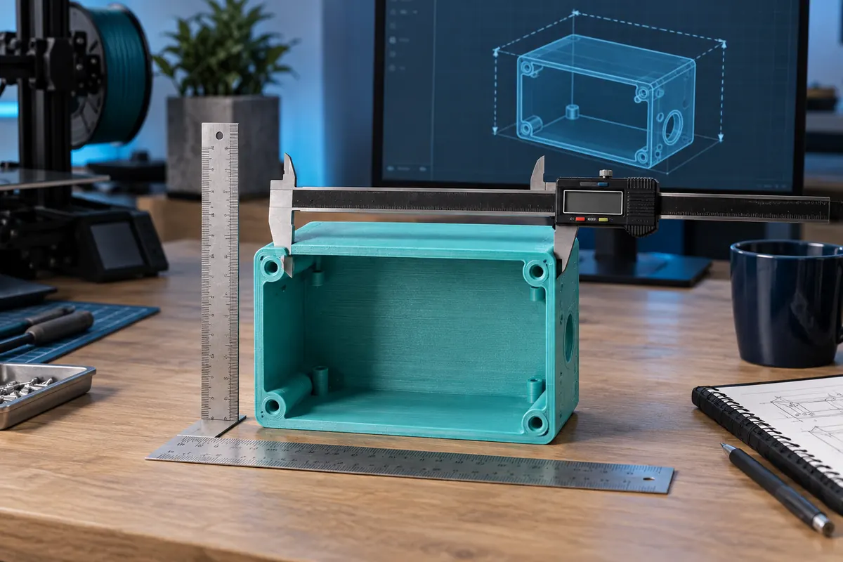
Start with the dimension you need to know
A model's overall width is useful for bed placement, but it does not answer whether a bolt fits a hole or whether a clip clears its mating feature. Write down the decision first: printer fit, scale verification, external size or a functional interface. Then choose the matching measurement. Overall extents can be taken from a bounding box. Local feature distances are better inspected in CAD or a mesh tool with explicit point-to-point measurements. Keeping these questions separate prevents a plausible outside size from being mistaken for a complete dimensional inspection.
Three axes, three dimensions
View data table
| Comparison | mm |
|---|---|
| X | 80 |
| Y | 50 |
| Z | 25 |
Establish intended units before interpreting numbers
Check the model description, CAD export settings or a known reference feature. STL does not reliably specify a standard unit, so an analyzer's millimetre assumption must be confirmed. A length of one coordinate unit could represent a millimetre or an inch in the author's workflow. An inch mismatch requires a known factor of 25.4; it should not be corrected by eye until the model merely looks reasonable. Retain the original file and record the evidence for the conversion. If a supplied screw hole has an expected nominal diameter, that is a better reference than judging the model thumbnail.
Read bounding dimensions without confusing position
For each axis, extent equals the maximum vertex coordinate minus the minimum. A model spanning X from ?10 to 30 has width 40 units. Moving it to span 0 to 40 does not change width. A rotation can change the axis-aligned extents, so measure in the intended print orientation. If one dimension is unexpectedly large, inspect for an outlying vertex, hidden shell or disconnected object before scaling the whole model. A single stray point can expand the box while most of the visible geometry remains small.
Check critical features independently
Identify interfaces, minimum walls, holes and dimensions that affect function. Measure their nominal geometry rather than assuming all details scale correctly from one outside length. A mesh can approximate a curved hole with facets, while CAD may retain the original analytic feature. Enlarging the mesh cannot reconstruct detail lost during export. Keep a short feature list with target values and the measurement method used. For a replacement bracket, this might include mounting-hole spacing, hole diameter and the distance from the mounting face to a locating edge.
Scaling and placement require fresh checks
Suppose a box measures 40 × 30 × 20 mm and is enlarged uniformly by 150%. Its new extents are 60 × 45 × 30 mm. The dimensions multiply by 1.5, but geometric volume multiplies by 3.375. Holes and designed clearances also change. After scaling, recheck functional features and the footprint including supports or brim. The model-scaling calculator previews uniform changes; the build-volume checker provides a preliminary rectangular fit. Neither guarantees that a resized connector still mates with its original counterpart.
Distinguish the model from the cooled print
Nominal file dimensions and manufactured dimensions answer different questions. Inspect the file before printing, then measure the cooled physical part with an appropriate instrument. First-layer bulging, proportional shrinkage, hole offsets and measuring pressure can create different discrepancies. Compare several sizes or locations before applying a global correction. For example, a constant 0.3 mm hole error is not equivalent to a one-percent scale error over all lengths. A traceable inspection records both nominal and measured values rather than silently replacing one with the other.
A practical approval sequence
Confirm units, orient the model, measure its overall extents, inspect the critical feature list and slice with the intended printer profile. Look through the preview for missing thin features or changed surfaces. Print a representative sample when fit matters, then compare cooled measurements with the design's actual requirement. Preserve the accepted file, orientation and scale factor. When any of those change, repeat the affected checks. This sequence makes dimension checking a concrete decision process rather than a screenshot of three numbers that says little about the part's function.
Measurement checklist
| Question | Check | Meaning |
|---|---|---|
| Does the part fit the bed? | Measure the final oriented bounding box. | Check supports and brim separately before approving placement. |
| Does the connector mate? | Inspect its local CAD feature and cooled sample. | Overall width cannot prove a hole or locating face is correct. |
| Is the scale correct? | Compare a known reference with intended units. | Preserve the evidence for any conversion or resizing operation. |
Can a bounding box measure every hole?
No. It gives overall axis extents. Inspect local interfaces separately in CAD or an appropriate measuring tool.
Do correct file dimensions prove the print will fit?
No. Print and measure a cooled sample for functional accuracy and distinguish process error from intended clearance.