
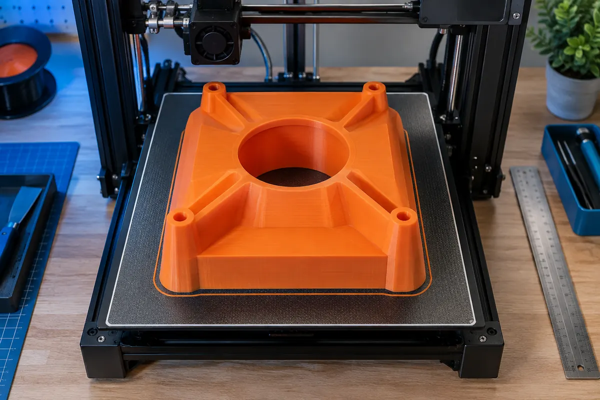
Use the real working envelope
Advertised width, depth and height describe a nominal space. The region available to a particular job may be smaller because of print-sheet shape, clips, excluded areas, tools or printer configuration. Start from the correct machine profile and verify the usable bed in its documentation. Do not borrow a profile from a visually similar printer. Record the current nozzle or tool setup when it affects reach. A model that fits the advertised dimensions still needs a complete placement check before it becomes a printable job.
Reserve space around the model
View data table
| Comparison | mm |
|---|---|
| Model width | 180 |
| Including brim | 190 |
| With clearance | 196 |
Measure after selecting an orientation
The axis-aligned model box depends on orientation. A tall part laid flat can reduce Z demand while increasing footprint and supports. Compare alternatives using their actual dimensions after rotation. Simply swapping width and depth examines a quarter-turn placement, not every possible tilted configuration. The bounding box includes the full extent of the part but not necessarily other structures generated later. It is a useful preliminary screen, particularly for scaling decisions, but it cannot optimise the orientation or determine surface quality and strength implications.
Reserve a deliberate margin
Choose a clearance that matches the real layout and machine constraints rather than assuming one universal safe gap. In the PrintTools Lab checker, X and Y receive allowance on both sides and Z receives allowance above the part. A 210 mm-wide part on a 220 mm rectangular bed with 5 mm each side exactly meets the simple width condition. At 6 mm clearance it requires 222 mm and fails. This arithmetic explains the selected assumption; it does not certify that a zero remaining margin is appropriate for your machine.
Check more than the model footprint
Supports, brims, rafts and wipe towers can occupy substantial additional space. Start routines may add a purge line away from the part. Generate these features before approving placement and examine the complete preview. A support structure can extend farther than the surface it supports, so outside model dimensions are not always sufficient. For multiple objects, inspect their combined arrangement and ancillary structures. A per-part fit calculation cannot be multiplied by quantity to decide how many fit on a plate.
Recognise non-rectangular and collision constraints
A circular bed's diameter is not equivalent to a rectangular region of the same width and depth. A square can fit those dimensions yet put its corners outside the circle. Likewise, a toolhead or gantry may interfere with geometry that lies within the nominal box. Sequential printing needs clearance around already completed parts and height-dependent collision checks. Use the slicer's correct machine geometry and the printer's prescribed workflow. The simple box tool intentionally excludes these constraints, so passing its conditions is evidence only for the stated rectangular approximation.
A practical layout comparison
Suppose your usable volume is 220 × 220 × 250 mm. A 200 × 150 × 100 mm model with the checker’s 5 mm clearance needs 210 × 160 × 105 mm and passes. Add a brim extending 8 mm on each horizontal side, and the footprint becomes 216 × 166 mm before any separate safety margin. You must now reconsider how brim and clearance are represented without counting the same margin twice. If rotating reduces footprint, examine new support and interface requirements before choosing that alternative.
Validate the exported job and changes
After selecting the layout, slice it, inspect maximum extents and check all generated auxiliary features. Preserve the profile, orientation and scale with the project. If the model, nozzle setup or support strategy changes, repeat the affected checks before using an old approval. Near the limits, use an appropriate machine-specific validation rather than relying on a screenshot of advertised dimensions. A successful fit decision combines geometry, usable machine envelope and the full intended printing process. It does not follow from three nominal numbers alone.
Placement approval checklist
| Item | Inspect | Limit |
|---|---|---|
| Part dimensions | Final orientation and scale. | Original CAD extents may describe another placement. |
| Full footprint | Supports, brim and wipe structures. | Model-only width excludes generated ancillary geometry. |
| Machine envelope | Real shape and excluded areas. | Nominal rectangular dimensions cannot represent every collision constraint. |
Does fitting the bounding box prove that a job is printable?
No. Check bed shape, auxiliary structures, machine restrictions and the complete sliced layout.
How should I handle brim and clearance?
Include the actual brim footprint and a separately justified margin without adding the same allowance twice.