
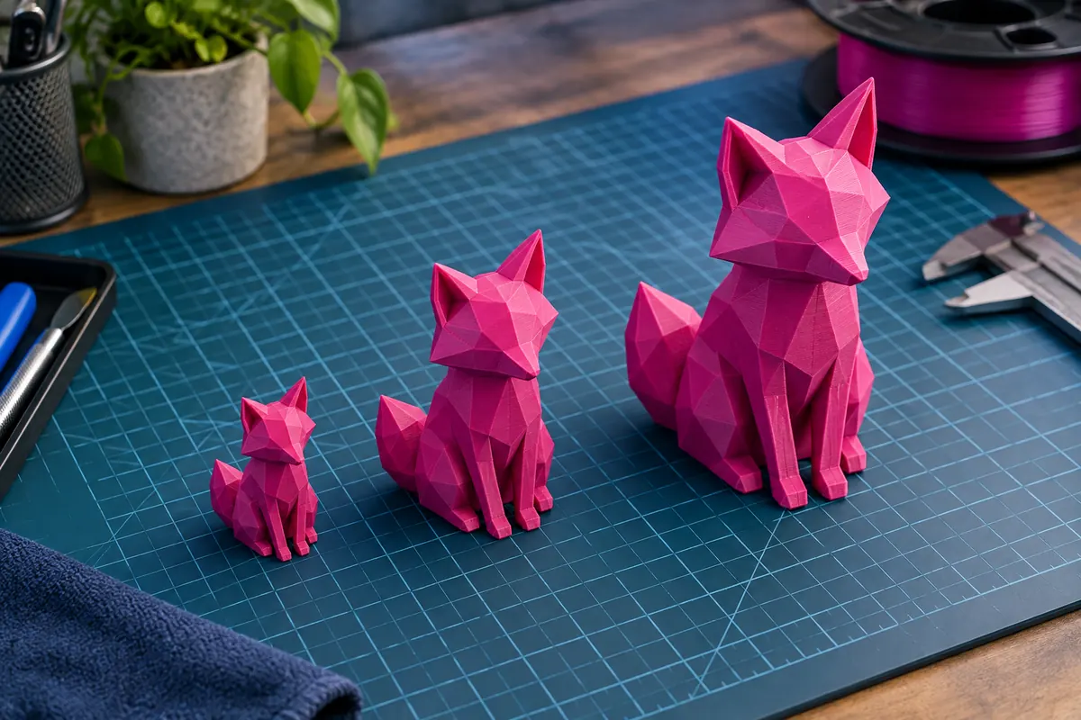
Technical context
Use uniform scaling for preserving proportions and check every mating feature afterward. Independent-axis scaling can distort holes, angles and fitted interfaces. An inch-to-millimeter conversion uses 25.4, but applying it without evidence can enlarge an already correct file drastically.
Doubling size multiplies volume by eight
View data table
| Comparison | × |
|---|---|
| Length | 2 |
| Area | 4 |
| Volume | 8 |
Practical workflow
Re-slice supports, walls and duration after resizing. Uniform geometric volume grows cubically, while printed consumption depends on fixed-width shells and infill. A small-scale model may lose thin details that printed reliably at its original size.
Calculation and units
Factor = desired/reference. Dimensions multiply by factor; solid volume by factor³, or sx × sy × sz for independent axes.
Worked example
40 × 20 × 10 mm uniformly scaled by 1.5 becomes 60 × 30 × 15 mm and solid volume grows by 3.375.
Validate the outcome
Re-slice mass and time. Check walls and joints; nonuniform scaling can make round holes elliptical.
Scale from a known reference and verify
A 40 mm width that needs 60 mm uses factor 60/40 = 1.5 or 150%. Keep all axes linked to preserve proportions and remeasure the reference afterward. Entering 60% instead would shrink the width to 24 mm. A factor-of-25.4 error suggests inches versus millimeters, but verify against design evidence before conversion; already-scaled exports and double conversions create other errors. Save an untouched original and the selected factor.
Functional features do not scale safely by default
A 0.4 mm clearance becomes 0.2 mm at 50% scale, but process errors do not necessarily halve. Thin walls, pins and snap sections also shrink and may vanish or become fragile. A visually correct assembly can therefore bind or fail. Redesign mating features in CAD when function must survive resizing, and validate actual fit with the intended material, orientation and profile rather than relying on the scaled surface alone.
Re-slice rather than scaling old consumption
Uniform solid volume grows with factor cubed: 1.5 scale means 3.375 volume. Sliced mass does not necessarily follow, because shell path widths and wall counts remain profile decisions and support can change. Re-slice after any resize, inspect the entire preview, update cost and remaining-stock checks, and verify build-space clearance including brim or tower. The geometry factor describes shape; the new slicing job establishes production demand.
Scale factor consequences
| Scale | Original40 mm width | New width | Solid-volume factor |
|---|---|---|---|
| 50% | 40 mm | 20 mm | 0.125 |
| 150% | 40 mm | 60 mm | 3.375 |
| 200% | 40 mm | 80 mm | 8 |
A resize checklist for functional assemblies
After setting scale from a known dimension, inspect walls, holes, snap features and mating clearances. Process error does not necessarily scale with the design, so a half-size clearance is not automatically printable. Rebuild functional details in CAD when necessary and check both pieces of a joint. Keep the original geometry and the resized revision rather than overwriting the only source.
Re-slice and verify total consumption, duration, support and occupied plate area including brim or tower. Solid-volume factor is only a geometric indicator; it is not an exact mass or time multiplier for infilled production. If units were corrected, remeasure a known feature before applying any additional desired resize. This prevents a double conversion being mistaken for an ordinary large model and makes the final scale decision reviewable.
Can I scale a snap-fit assembly like a decorative model?
Uniform scaling preserves proportions, but it changes clearance, wall flexibility and tiny feature dimensions while process errors may remain similar. A visually correct scaled assembly can bind or break. Revisit the functional geometry in CAD and test both mating pieces under the intended material and orientation. Keep model factor and shrinkage compensation separate; one resizes the design while the other attempts to correct a measured production effect.
Is geometric volume a reliable new filament estimate?
It describes ideal solid geometry under valid mesh conditions. An infilled print includes profile-dependent shells, sparse paths, supports and startup or purge, so its mass need not scale cubically. Re-slice after resizing and use the resulting total consumption for stock and cost checks. Validate units before applying an additional factor and inspect thin features and plate clearance. The scale calculator's volume factor is explanatory geometry, not an exact print-demand prediction.