
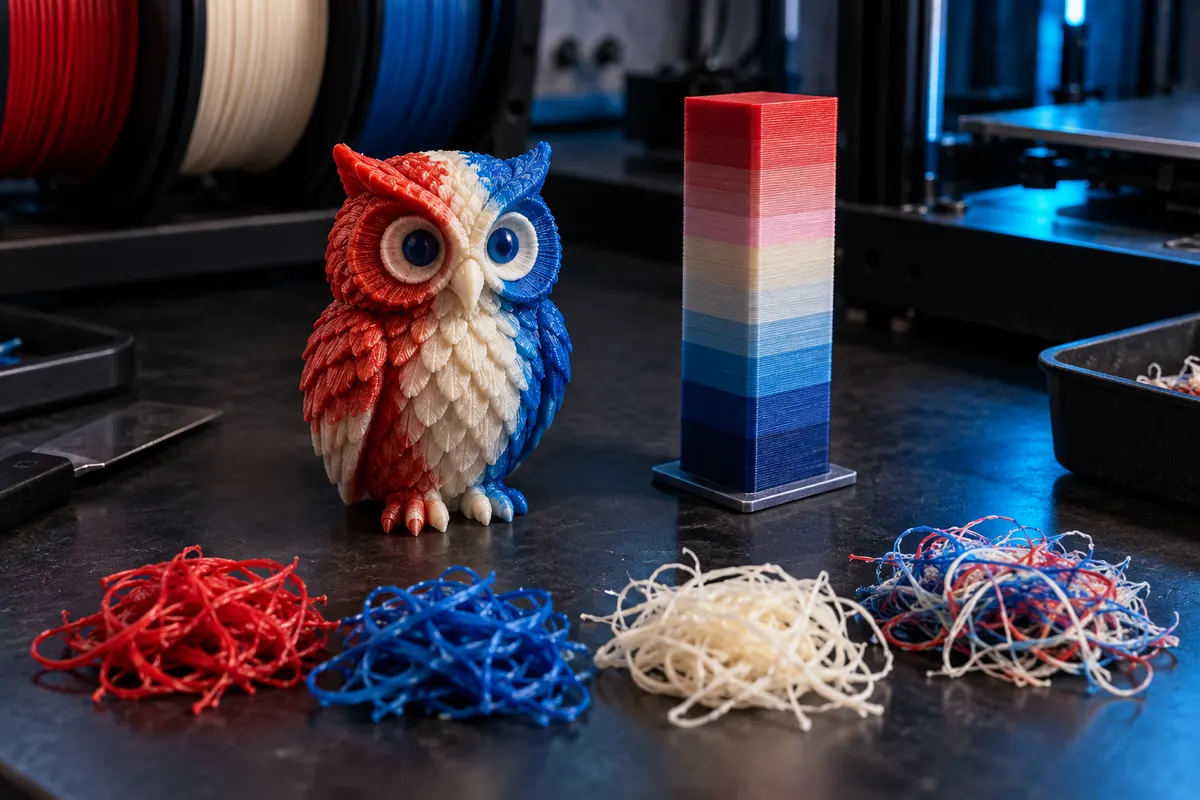
Technical context
Examine directional purge volumes and the whole-plate slicer breakdown. Changing orientation or moving color boundaries can reduce transitions. Batching copies may spread tower overhead, but may also increase failure exposure and total plate time; compare actual sliced variants.
Transitions add purge material
View data table
| Comparison | g |
|---|---|
| 20 changes | 10 |
| 50 changes | 25 |
| 100 changes | 50 |
Practical workflow
Purging into infill or a sacrificial object is useful only where color bleed and material compatibility are acceptable. Do not count repurposed purge as cost-free; it still consumes a spool. Reduce volume through validated transition tests rather than blindly zeroing the purge matrix.
Calculation and units
Purge g = changes × mm³/change × density/1,000. Waste fraction = waste/(useful + waste).
Worked example
200 changes × 80 mm³ at 1.24 density = 19.84 g. At 0.025/g this costs 0.496; with 40 g useful material the fraction is 33.2%.
Validate the outcome
Use slicer transition matrices; add tower mass only if not already counted. Lower purge only after checking colors and bonding.
Establish a complete consumption baseline
Before reducing anything, record useful model mass, purge or wipe structures, supports and other ancillary material from the current slice. Check whether the displayed total already includes all categories. A purge calculator estimate should not be added again to a total that contains the same waste. Photograph the accepted result and save the profile. The objective is lower consumption per accepted part, not the smallest purge number regardless of colour contamination, interface quality or failed prints.
Colour changes are a directional process
Changing from one colour to another may require a different clearing amount from the reverse transition. Material combinations and the extrusion system also affect the usable result. A global percentage reduction treats those transitions as if they were identical, which may be inappropriate. Use the relevant purging workflow and test the actual direction pairs. Record visible contamination and any material-interface consequence. A transition that looks acceptable on a hidden region can still be wrong on a visible face or an area with a functional requirement.
Reduce unnecessary transitions at the design stage
Inspect where colours occur across layers. Small isolated coloured details can create many changes even when their useful mass is tiny. A design revision that moves decoration or separates components may reduce changes, but it also alters appearance or assembly. Evaluate that tradeoff with the intended design requirements. Do not silently remove a required colour feature just to improve a waste figure. Compare actual resliced transition counts and consumption rather than assuming a geometric simplification saves a fixed percentage.
Batching can spread some overhead
When multiple compatible objects share a plate, some colour changes may serve several parts. That can reduce change-related material per accepted part, but the result depends on layer alignment and toolpath strategy. A larger batch also ties up more material and may expose more pieces to one failure. Compare totals and expected accepted quantity, not simply mass divided by planned quantity. Check build-volume arrangement, supports and completion reliability. The batch-cost tool can help interpret overhead once the new actual slice is available.
Alternative purge placement needs validation
A slicer may offer strategies that place some transition material in non-visible regions or other appropriate paths. Use only supported options and inspect the preview carefully. Contaminated material can affect appearance or properties, and hiding it is not automatically harmless. A wipe structure may still be necessary for stable tool changes. Validate the actual part after a deliberate reduction. Keep each method's limits visible rather than describing waste as eliminated when it has merely been moved somewhere else in the object.
Quantify a transparent example
With 100 changes at 300 mm³ per change, the planned purge is 30,000 mm³, or 30 cm³. At a stated density of 1.24 g/cm³ this is 37.2 g; at 25 per kilogram it costs 0.93. These numbers describe an illustrative assumption, not a universal transition requirement. If a tested revision lowers each relevant change to 250 mm³, the model gives 31 g and 0.775. Confirm colour and interface acceptance before calling the 6.2 g difference a usable saving.
Approve the lower-waste process
Print a representative job with the revised setup and compare contamination, extrusion restart, surfaces and function with the baseline. Record added finishing or rejected parts. Carry the actual sliced masses into multi-material and total-cost calculations with consistent prices and no duplicate waste allowance. Save accepted directional values and design settings together. Recheck after material, nozzle or extrusion-system changes. Sustainable reduction is a repeatable lower cost per successful part, with quality requirements retained and the basis of each saving documented.
Is one purge value suitable for every colour direction?
Not necessarily. Validate the actual directional transitions, system and material combination.
Does less purge always mean a lower accepted-part cost?
No. Contamination, rejects and extra finishing can outweigh the material saving.