
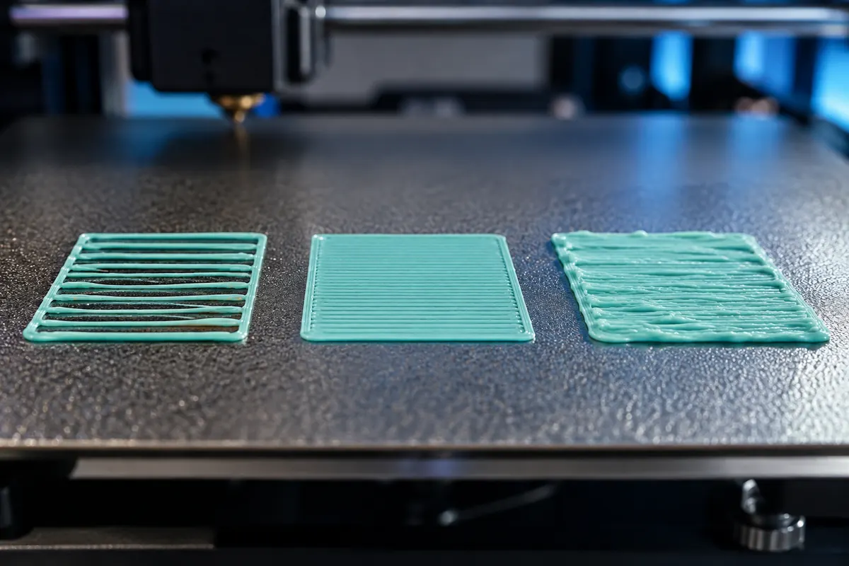
Technical context
Separate round strands suggest inadequate flattening; scraping, ridges or interrupted flow can suggest excessive closeness. Verify surface cleanliness, correct sheet/material pairing and manufacturer calibration before changing extrusion. A dirty patch can mimic a leveling problem at one location.
Practical workflow
Use a small test spanning the problematic area and inspect before a long job. Some printers automatically establish nozzle position, so their procedure differs from manual-offset machines. Do not apply a universal Z-offset or adhesion product without checking surface compatibility.
Calculation and units
New ratio = current ratio × target/measured wall. 1.00 means 100%; slicer and firmware multipliers can multiply.
Worked example
1.00 ratio, 0.45 mm target and 0.47 mm measured suggest 0.95745. Reprint and inspect surfaces and dimensions.
Validate the outcome
Measure cooled samples repeatedly. Large corrections may indicate hardware or feed issues instead of a simple flow mismatch.
Observe adhesion and line shape separately
A first layer can fail to stick, show separated lines, form ridges or vary across the bed. Describe the pattern before changing a setting. Poor adhesion does not prove the nozzle is too high, and a rough surface does not always prove excessive flow. Photograph the same small test in several bed locations and record sheet, material and profile. This baseline helps separate local geometry from a global extrusion issue. Stop a clearly failing test rather than continuing to print a large part on an unstable foundation.
Verify the correct sheet and preparation
Use the surface intended for the material and follow its documented cleaning or separation procedure. Oil, residue and incompatible preparation can affect adhesion independently of nozzle height. Do not apply one generic solvent or adhesive to every sheet. Check that the sheet is correctly seated and that debris beneath it is not altering its position. A prepared surface should be evaluated with the same material and conditions each time. Document changes so a later improvement is not falsely attributed to a different Z setting.
Check the printer's actual calibration workflow
Use the procedure for your machine, sensor and firmware rather than copying an offset from another model. A manually tuned i3 workflow and an automatically measured tool system may require different actions. Confirm relevant probes or references are clean and installed correctly according to their instructions. Repeatedly changing a global offset can hide a local bed or sheet problem. If one area is good and another is not, investigate the spatial pattern before assuming one universal number will correct the whole surface.
Read the printed lines carefully
Separated narrow lines can suggest insufficient contact or material, while ridges and displaced plastic can suggest excessive compression or deposition. These observations are clues, not a full diagnosis. Compare single lines with adjacent filled regions and inspect the start of extrusion. A dirty or partially obstructed nozzle can change line shape. Flow and width settings also influence the pattern. Adjust one relevant variable using the documented calibration test, then compare again. Avoid trying to fix global material flow by excessive first-layer compression.
Keep first-layer geometry explicit
First-layer height, width and speed can differ from normal-layer settings. A profile change that raises width or height also raises demanded material volume at the same speed. For example, 0.50 mm width × 0.25 mm height × 30 mm/s gives 3.75 mm³/s in the rectangular approximation. This is not a recommended universal setting; it shows the units and interaction. Use your actual profile values and inspect whether the extrusion system can supply them consistently before interpreting gaps as a bed-level problem.
Thermal and timing conditions need consistency
Run comparisons under repeatable heating and preparation conditions. A test made before the machine's intended preparation is complete may not represent its usual printing state. Temperature choices must remain compatible with material and surface guidance. If changing temperature helps adhesion, verify it does not cause other material or surface problems. An enclosure or draft condition can influence results, but any change must be suitable for the whole machine. Do not use uncontrolled heating as a substitute for identifying contamination, incorrect calibration or local bed variation.
Make the smallest useful correction
Choose one cause supported by the observations, perform the corresponding documented adjustment and print the same comparison again. A corner-only problem, a start-only problem and an everywhere problem should not receive the same undifferentiated fix. Record old and new settings. If one change improves contact but creates heavy ridging, inspect whether you passed the useful range or whether a second cause remains. A reliable first layer should show consistent placement and adhesion across the region actually used by the job.
Validate with the production footprint
A small central square can pass while a wide part reaches untested areas. After the initial correction, test the relevant footprint or representative placement and inspect all generated adhesion features. Check that removal and the lower surface remain acceptable after cooling. Do not assume that maximum stickiness is always the goal; some material-surface combinations require separation guidance. Save the accepted preparation and profile together. First-layer reliability comes from a repeatable whole procedure, not a single offset whose successful conditions were never recorded.
Separate first-layer observations
| Pattern | Initial check | Do not conclude |
|---|---|---|
| Only one bed region fails | Sheet seating and spatial calibration pattern. | That every material needs a larger global flow factor. |
| Lines fail immediately everywhere | Surface preparation, contact and feed reliability. | That a chamber change alone fixes the cause. |
| Layer starts well, then corners lift | Timing, thermal conditions and geometry. | That maximum adhesion necessarily prevents deformation. |
Does poor adhesion always mean the nozzle is too high?
No. Surface preparation, material compatibility, extrusion and local machine geometry can create similar symptoms.
Can a central test approve the whole bed?
Not by itself. Validate the footprint and locations used by the intended job.