
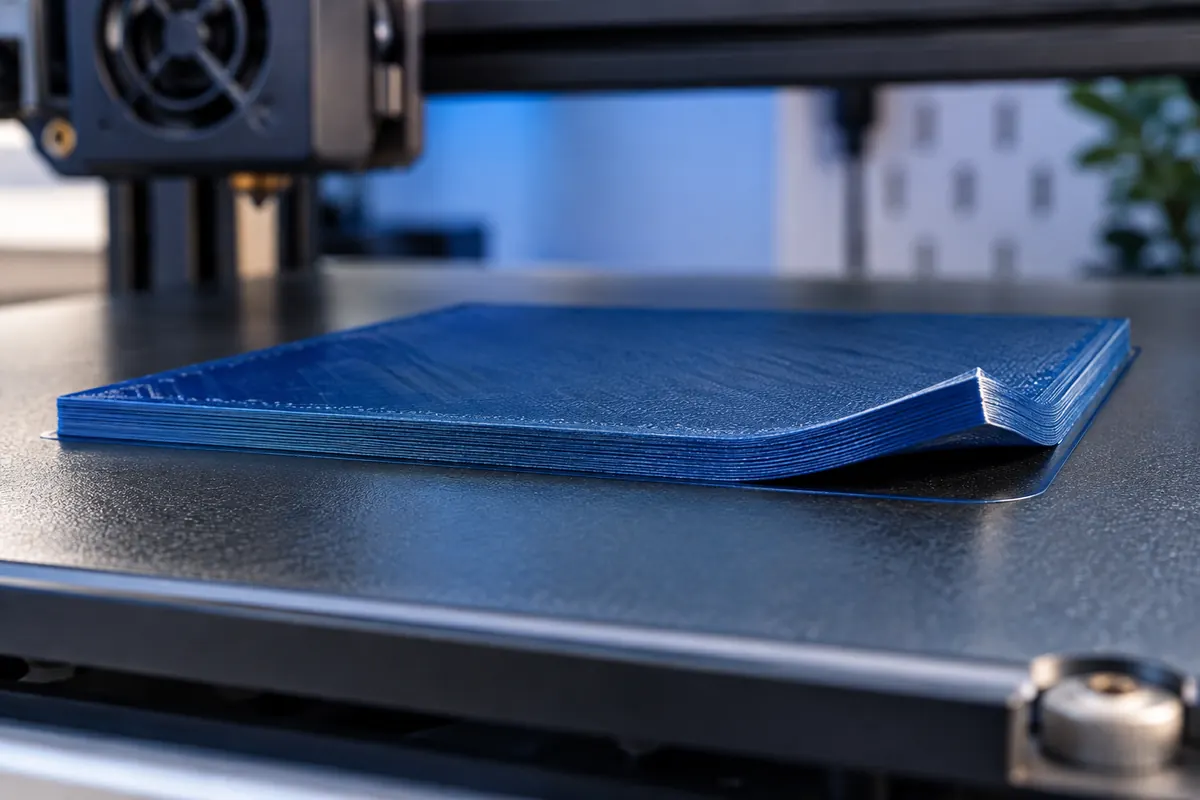
Technical context
Check first-layer adhesion, appropriate bed surface and the material's environmental requirements. Large continuous bases and sharp corners can concentrate stress. A compatible brim or redesigned geometry can help, but do not seal a printer into an enclosure without considering its manufacturer's thermal requirements.
Practical workflow
Change one cause at a time and inspect flatness after cooling. Scaling compensation changes dimensions but cannot flatten lifted corners. A warmer process may reduce temperature gradients while creating other material or hardware issues, so validate the complete result.
Calculation and units
Scale = target/measured. Shrinkage = (nominal ? measured)/nominal. Compensation for fraction s = 1/(1 ? s).
Worked example
100 mm measured at 99 mm needs 101.0101%. A 10 mm detail at 9.8 mm needs another factor, suggesting other errors.
Validate the outcome
Measure several sizes and directions. Use hole compensation or CAD clearance for local mating errors.
Separate lifting from a height-calibration defect
Warping describes deformation and lifting associated with the printing and cooling process. A poor first layer can initiate lifting without identifying the whole cause. Document when the corner rises, which locations are affected and whether the part's bottom remains attached elsewhere. A photo after the job is useful, but observations during printing can distinguish early adhesion failure from later distortion. Keep material, profile, orientation and environment recorded. Do not immediately increase adhesion until removal becomes difficult while ignoring the deformation that remains.
Check the initial foundation
Use a compatible clean surface and the correct first-layer procedure for the printer. Confirm the part is actually placed within usable bed space and that preparation follows surface guidance. A small central test cannot approve a large corner-to-corner footprint. If lifting occurs immediately, investigate line contact and surface condition before changing enclosure or cooling settings. If the first layer starts well and lifting develops later, the thermal and geometric history deserves closer attention. This timing distinction makes the troubleshooting sequence more focused.
Control the environment appropriately
Drafts or inconsistent thermal conditions can change how different regions cool. An enclosure may be relevant for some material and machine combinations, but its use must follow the equipment's capabilities. Do not assume every printer should be enclosed or exposed to the same chamber temperature. Keep surrounding conditions consistent while comparing tests. Cooling changes can also affect overhangs and layer quality, so evaluate more than the lifted corner. A modification that removes one symptom but damages the rest of the part is not a validated process improvement.
Geometry and orientation influence stress
Long continuous shapes, sharp corners, large solid regions and changing cross-sections can behave differently during cooling. Consider a CAD or orientation revision when the function allows it. A rounded corner or segmented layout may change the problem, but each also changes the design or production process and needs approval against requirements. Splitting a part introduces joints and assembly work. Compare these alternatives with their full consequences instead of assuming a stronger brim can solve every geometry-related distortion.
Use adhesion structures as explicit experiments
A brim or other supported adhesion feature can increase contact area, but it does not guarantee elimination of internal stress. Inspect its actual extent and build-volume fit. Compare the same part with and without the planned change while keeping other relevant settings fixed. Record added material, removal time and bottom-surface effects. Apply adhesives or separation layers only according to material and sheet guidance. The goal is reliable printing and appropriate removal, not simply making the part impossible to detach.
Check infill, walls and cooling changes separately
A profile revision that simultaneously changes infill, wall count, temperature and fan behaviour cannot reveal which change helped. Choose one supported hypothesis and keep a baseline. Large solid areas and their deposition sequence can matter differently from a sparse part. Inspect the toolpath preview and compare representative geometry rather than a unrelated small tower. Use the wall and flow calculators to understand geometric changes, but do not present those numbers as a warping predictor. They do not model thermal contraction or the part's mechanical stresses.
Measure after cooling and removal
A part that stayed attached can still distort after release. Inspect cooled geometry, mating surfaces and function, not only whether corners remained on the bed during printing. Document deviation at several positions and compare repeat parts. If a scale change is proposed, distinguish proportional shrinkage from curved deformation: a uniform scale cannot flatten a warped surface. The shrinkage tool provides a ratio correction, not a thermal simulation or repair of a bent part.
Retain a reproducible solution
After finding a candidate, repeat the job or relevant portion under ordinary production conditions. Save the accepted surface preparation, profile, orientation and environment together. Reassess when material, footprint or machine setup changes. If the part's function allows a design revision, document it as such rather than silently treating it as a printer setting. Reliable prevention comes from matching the whole process to the actual geometry and material, with known limits instead of a universal anti-warping recipe.
Separate the observed mechanisms
| Observation | Check | Useful comparison |
|---|---|---|
| Immediate lift | First-layer contact and compatible surface. | Repeat the same footprint after one documented correction. |
| Later lift or bend | Thermal history and geometry. | Compare controlled conditions and the cooled shape. |
| Stays attached but bends after removal | Released geometry and functional interface. | Measure repeat samples instead of judging bed contact alone. |
Can scaling fix a warped bottom?
Uniform scaling cannot flatten curved deformation. Separate shape distortion from a proportional dimensional error.
Does a larger brim guarantee success?
No. It changes adhesion area but does not prove control of the underlying process or safe removal.