
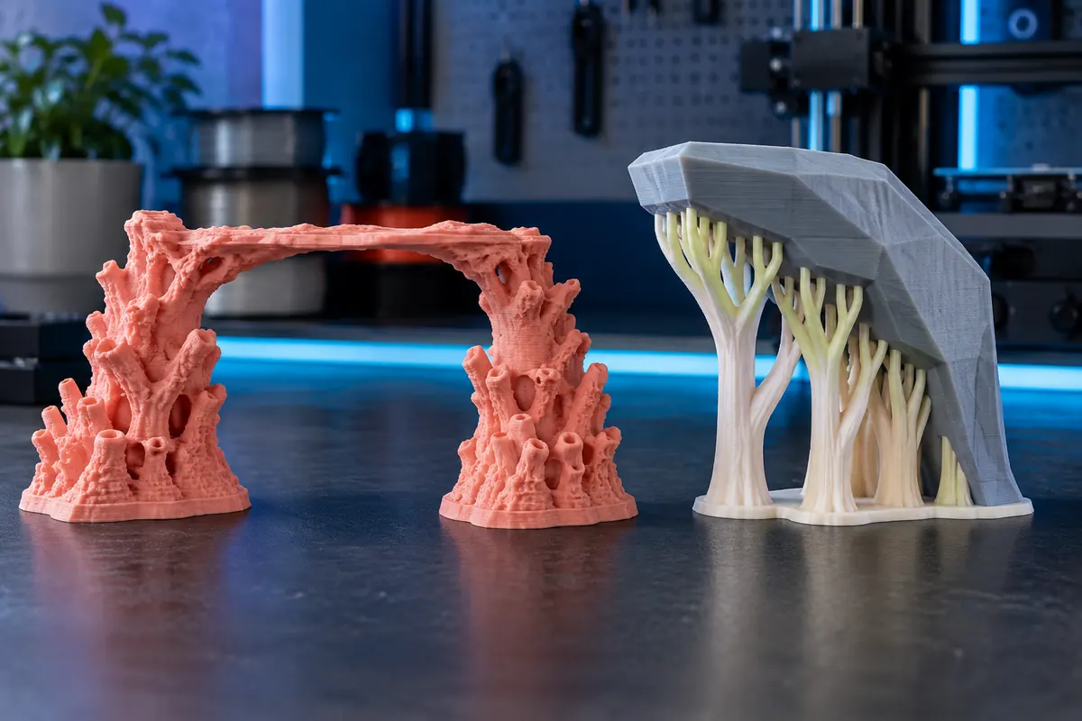
Technical context
Identify whether a region has two anchors or an unsupported island. Cooling, speed and bridge extrusion influence a real span, while support interface and separation determine supported surface quality and removability. No universal maximum bridge length fits every material and printer.
Practical workflow
Try reorientation or a designed chamfer before adding large support volumes. For a long span, localized intermediate support can reduce unsupported distance. Print a representative test and compare final surface requirements, removal effort and total material consumption.
Calculation and units
Dimensions = max ? min coordinates. Closed oriented mesh volume = sum(a · (b × c)/6). Closure and intersections affect validity; a numerical sum alone is insufficient.
Worked example
X from ?10 to 30 gives 40 coordinate units. If millimeters are intended, width is 40 mm; box volume is not object volume.
Validate the outcome
Confirm units and repair geometry. Use slicer consumption for hollow or infilled prints and never invent STL print time.
A bridge and an overhang are different situations
A bridge spans a gap between supported regions, while an overhang extends beyond support from the previous layer. Their geometry and deposition conditions differ. A part can contain both, so deciding that a printer bridges well does not justify removing every support. Identify the actual unsupported regions in the slicer preview and distinguish short spans, open edges and sloped surfaces. Use a representative test rather than a universal angle or span claim. Material, cooling, path direction and profile affect the useful result.
Start with orientation and function
An orientation that reduces supports can improve access and save material, but it can also change layer direction, visible surfaces and load behaviour. List the faces and interfaces that must remain accurate before choosing the orientation. A mounting surface may matter more than a decorative underside. Compare a supported placement with a rotated alternative in the preview and note any new bridge or overhang. The best choice meets the function with acceptable finishing, not merely the smallest support mass displayed by the slicer.
Bridge paths need reliable anchors
Inspect where the first spanning lines begin and end. A gap between secure regions is different from a cantilevered edge with no second anchor. Check the generated path direction and whether the intended line spans the gap or follows another strategy. A sagging first bridge layer may affect later layers and local dimensions even when the top eventually looks closed. Evaluate the underside and function after cooling. A visually complete roof is not proof that the opening below retains its required height.
Compare supports by total effort
Supports add material and printing time, but they may preserve a critical surface or reduce a failure risk. Removal can leave marks, damage thin features or require active work. Accessible support is different from trapped support in a closed cavity. Inspect removal paths before printing. If soluble or interface material is planned, use its actual consumption and handling process in the cost comparison. Material savings alone do not decide whether a no-support alternative is cheaper once finishing and rejects are included.
Run a relevant quality comparison
Choose a coupon containing the span, edge or underside that matters to the project. Keep nozzle, material and relevant profile stable while comparing one change. Evaluate sag, surface, clearance and removal damage against the requirement. A sample that looks good at one short span does not prove performance across a longer opening. Record the geometry, path direction and acceptance result, then validate on the production part. The purpose is to find a usable strategy for the actual feature rather than a maximum advertised bridging distance.
Use the tools after slicing
Take the new support-inclusive mass and duration from each sliced alternative into the cost calculator. For two materials, use the separate material contributions rather than blending prices. If orientation changes dimensions, run the model and build-volume checks again. Do not invent support mass or duration from the STL's solid volume. Compare at least one practical outcome measure such as usable interface quality or finishing minutes alongside material. A complete decision combines geometry, validated print behaviour and the total effort needed to obtain an accepted part.
Does good bridging mean no supports are needed?
No. Bridges, overhangs and cantilevers have different geometry. Inspect each relevant region and its functional requirement.
Should I always choose the smallest support mass?
Not alone. Compare finishing, quality and failure cost as well as material and print time.